Maps are mostly made up of lines, as well as the occasional polygon thrown in. Unfortunately, drawing lines is a weak point of OpenGL. The GL_LINES drawing mode is limited: it does not support line joins, line caps, non-integer line widths, widths greater than 10px, or varying widths in a single pass. Given these limitations, it’s unsuitable for the line work necessary for high-quality maps. Here’s an example of GL_LINES:

Additionally, OpenGL’s antialiasing (multisample antialiasing) is not reliably present on all devices, and generally is of poor quality anyway.
As an alternative to native lines, we can tessellate the line to polygons and draw it as a shape. A few months ago, I investigatedvariousapproaches to line rendering and experimented with one that draws six triangles per line:
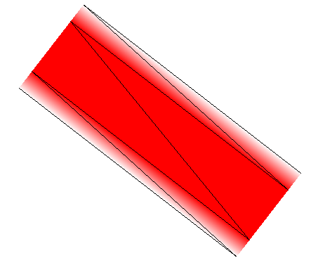
Two pairs of triangles form a quadrilateral gradient on each sides, and a quadrilateral in the middle makes up the actual line. The gradients provide antialiasing, so that the line fades out at the edges. When scaled down, this produces high quality lines:
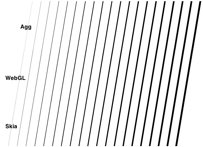
Unfortunately, generating six triangles per line segment means generating eight vertices per line segment, which requires a lot of memory. I worked on an experiment that uses only two vertices per line segment, but this way of drawing lines requires three draw calls per line. To maintain a good framerate we need to minimize the number of draw calls per frame.
Attribute interpolation to the rescue
OpenGL’s drawing works in two stages. First, a list of vertices is passed to the vertex shader. The vertex shader is basically a small function that transforms every vertex (in the model coordinate system) to a new position (the screen coordinate system), so that you can reuse the same array of vertices for every frame, but still do things like rotate, translate, or scale the objects.
Three consecutive vertices form a triangle. All pixels in that area are then processed by the fragment shader, also called the pixel shader. While the vertex shader is run once for every vertex in the source array, the fragment shader is run once for every pixel in a triangle to decide what color to assign to that pixel. In the simplest case, it might assign a constant color, like this:
void main() {
    gl_FragColor = vec4(0, 0, 0, 1);
}
The color order is RGBA, so this example renders all fragments as opaque black. If we rendered lines by creating polygons from those lines, and assign a constant color to all pixels in that polygon, we’d still have horribly aliased lines. We need a way to decrease the alpha value from 1 to 0 as the pixels approach the polygon’s border. When transforming vertices in the vertex shader, OpenGL allows us to assign attributes to every vertex, for example:
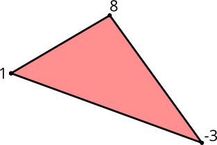
These attributes are then passed on to the pixel shader. The interesting part is this: since a pixel can’t be directly associated with a single vertex, the attributes are interpolated between three discrete values according to the pixel’s distance to the three vertices that make up the triangle:
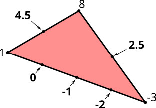
This interpolation produces gradients between the vertices. This is the basis for the line drawing method I’m going to describe.
Requirements
When drawing lines, we have a couple of requirements:
- Variable line width: We want to change the line width in every frame we draw so that when the user zooms in/out, we don’t have to tessellate the line to triangles over and over again. This means that the final vertex position must be calculated in the vertex shader at render time and not when we set up the scene.
- End caps (butt, round, square): This describes how the ends of lines are drawn.
- Line joins (miter, round, bevel): This describes how joints between two lines are drawn.
- Multiple lines: For performance reasons, we want lines with varying widths and colors in one draw call.
Line Tessellation
Since we want to change the line width dynamically, we cannot perform the complete tessellation at setup time. Instead, we repeat the same vertex twice, so that for a line segment, we end up with four vertices (marked 1-4) in our array:
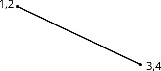
In addition, we calculate the normal unit vector for the line segment and assign it to every vertex, with the first vertex getting a positive unit vector and the second a negative unit vector. The unit vectors are the small arrows you see in this picture:
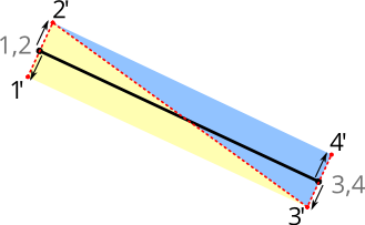
In our vertex shader, we can now adjust the line width at render time by multiplying the vertex’s unit vector with the line width set for that draw call, and end up with two triangles, visualized in this picture by the red dotted line.
The vertex shader looks something like this:
attribute vec2 a_pos;
attribute vec2 a_normal;

uniform float u_linewidth;
uniform mat4 u_mv_matrix;
uniform mat4 u_p_matrix;

void main() {
    vec4 delta = vec4(a_normal * u_linewidth, 0, 0);
    vec4 pos = u_mv_matrix * vec4(a_pos, 0, 1);
    gl_Position = u_p_matrix * (pos + delta);
}
In the main function, we multiply the normal unit vector with the line width to scale it to the actual line width. The correct vertex position (in screen space) is determined by multiplying it with the model/view matrix. Afterward, we add the extrusion vector so that the line width is independent of any model/view scaling. Finally, we multiply by the projection matrix to get the vertex position in projection space (in our case, we use a parallel projection so there is not much going on, except for scaling the screen space coordinates to the range of 0..1).
Antialiasing
We now have line segments of arbitrary width, but we still don’t have antialiased lines. To achieve the antialiasing effect, we’re going to use the normal unit vectors, but this time in the pixel shader. In the vertex shader, we just pass through the normal unit vectors to the pixel shader. Now, OpenGL interpolates between both normals so that the calculated vector we receive in the pixel shader is a gradient between the two unit vectors. This means they are no longer unit vectors, since their length is less than one. When we calculate the length of the vector, we get the perpendicular distance of that pixel from the original line segment, in the range of 0..1. We can use this distance to calculate the pixel’s alpha value. If we factor in the line width, we just assign the opaque color to all distances that are within the line width, minus a “feather” distance (see image below). Between linewidth - feather and linewidth + feather, we assign alpha values between one and zero, and to all fragments that are further than the unit vector away from the line, we assign an alpha value of zero (right now, there are no pixels that fulfill that property, but we’ll encounter them soon).
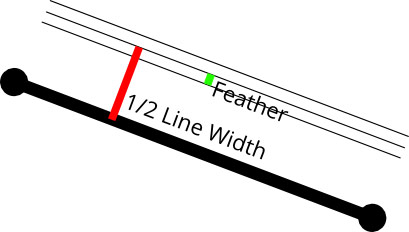
Apart from the line width, we can also vary the feather distance to get blurred lines, or shadows. We can reduce it to zero to have aliased lines. A feather value of 0.5 produces regular antialiasing that looks very similar to what Agg produces. A feather value between 0 and 0.5 produces results mimicking Mapnik’s gamma value.
Line Joins
The technique above works for singular line segments, but in most cases we’re drawing lines composed of several segments joined together. When joining line segments, we have to choose a line join style and move the vertices accordingly:
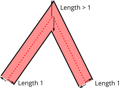
Earlier we calculated the normal of the line segment and assigned that to the vertex. This no longer works in the case of line joins because we actually need to calculate a per-vertex normal, rather than a per line segment normal. The per-vertex normal is the angle bisector normal of the two line segment normals.
Unit vectors for line joins also don’t work because the distance of the vertex from the line at join locations is actually further away than one. So rather than using the angle bisector unit vector, we just add the line segment unit vectors, which results in a vector that is neither a unit vector nor a normal. I call it an extrusion vector.
Unfortunately, we now have another problem: extrusion vectors are no longer normal to the line segment, so interpolation between two of them will not yield a perpendicular distance. Instead, we introduce another per-vertex attribute, the texture normal. This is a value of either 1 or -1, depending on whether the normal points up or down. This is of course not an actual normal because it has no orientation in 2D space, but it’s sufficient for achieving interpolation between 1 and -1 to get our line distance values for the antialiasing.
Since we don’t want to introduce yet another byte, of which we’d effectively use only a single sign bit, we encode the texture normal into the actual vertex attribute. The vertex attributes use 16-bit integers (-32768..32767) that are big enough to hold our typical vector tile coordinates of 0..4095. We double each coordinate (0..8190) and then use the least significant bit to store the texture normal. In the vertex shader, we extract that bit and use the model/view matrix to scale our coordinates down to the actual size.
To save memory, we encode the extrusion vectors with one byte per axis, so we have an (integer) range of -128..127 for every axis. Unfortunately, extrusion vectors can grow arbitrarily long for line joins because the extrusion vector length grows to infinity as the angle gets more acute. This is a common problem when drawing line joins, and the solution is to introduce a “miter limit”. If the extrusion vector gets longer than the miter limit, the line join is switched to a bevel join. This allows us to scale up the floating point normal dramatically so that we retain enough angle precision for the extrusion vector.
Mapbox GL
Look for future blog posts as we talk about more of the design and engineering work that has gone into Mapbox GL. Lines are just a small but necessary part of the bigger picture of what goes into high-quality custom maps rendered in realtime on the device.